How to create Non-Rectangular Viewports
Here is a free tutorial how to create Non-Rectangular Viewports in AutoCAD
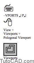
You can draw non-rectangular viewports directly with straight edge segments using the Vports Polygonal option.

You can also draw a 2D closed shape on the PAPER above a viewport and use this object to clip the viewport.
You can display model objects in detailed views at a larger viewport scale than objects displayed in the original VIEWPORT.
- first Scale the clipped VIEWPORT to make it larger.
- then change the viewport scale of the clipped viewport by the same factor used to enlarge the clipped viewport.
- you will use this technique in the next exercise.
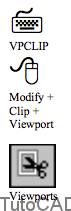
Use the Vpclip command to clip an existing viewport using an existing closed 2D object
- you are prompted to select a VIEWPORT.
- then you can either use the Polygonal option to draw a straight sided polygon shape or you can select an existing 2D object.
- valid 2D clipping objects include closed POLYLINES, CIRCLES, ELLIPSES, closed SPLINES, and REGIONS.
- you can also use the Vpclip Delete option to convert a clipped VIEWPORT back to a rectangular VIEWPORT.

The easiest way (used in the next exercise) to clip an existing VIEWPORT using an existing 2D object is to use a shortcut
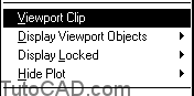
- make sure the PAPER button is in the status bar
- select the desired VIEWPORT when no command is running.
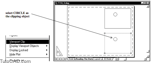
- right-click to invoke a shortcut, select the Viewport Clip option and then select the clipping object.
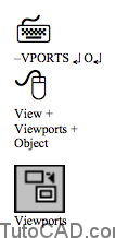
You can also use the Object option of Vports to “convert” an existing closed 2D object into a new VIEWPORT.
- you are prompted to select an object (closed 2D shape) and the new VIEWPORT is automatically clipped to this shape.
Practice tutorial: creating non-rectangular viewports in AutoCAD
1- Continue in the same drawing from the previous exercise.
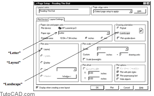
2- Left-click in the Layout1 tab. Select the Plot Device tab and use the HP LaserJet.pc3 device (or another device that your instructor tells you to use) and change the layout name to Reading The Dial. Then pick the Layout Settings tab and make sure the settings are as shown. Then pick OK.

3- Pick Edit + Clear and select the viewport that was automatically created and press <enter> to Erase it.
4- Make VIEWPORT the current layer.
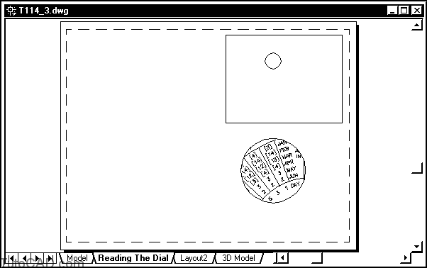
5- Pick View + Viewports + 1 Viewport and pick two corner
points near P1 then P2 to make a new viewport.

6- Pick View + Zoom + Window and pick near the same two points so your viewport almost fills your screen.
7- Left-click on PAPER in the status bar to switch to MODEL.
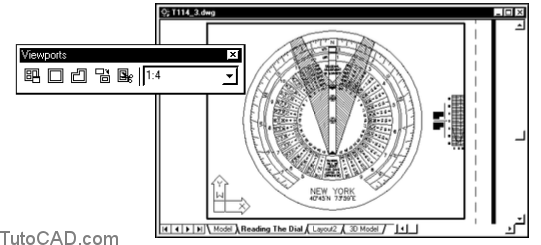
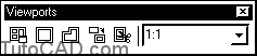
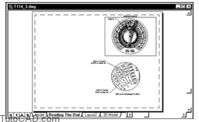
8- Select 1:4 as the viewport scale in the Viewports toolbar.
9- Use Pan to center the dial as shown in the viewport below.
10- Pick Format + Layer. Select DATA and Shadow AM then check the Freeze in active viewport box and pick OK.
11- Left-click on MODEL in the status bar to switch to PAPER.
12- Make DIMENSIONS the current layer.
13- Pick Draw + Circle + Center,Radius and click near P1 below as the center point and enter 0.3 as the radius.

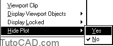
14- Select the viewport border to display the grips & right-click to invoke a shortcut. Select Hide Plot then pick Yes.
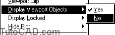
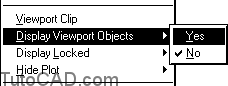
15- Select the viewport again & right-click to invoke a shortcut. Select Display Viewport Objects then pick No.
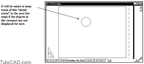
16- Pick View + Zoom + All to see the rest of the page.
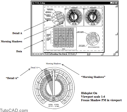
17- Pick Modify + Copy and select the CIRCLE & VIEWPORT object then press <enter> to continue. Pick two points by eye to copy these objects approximately as shown below.
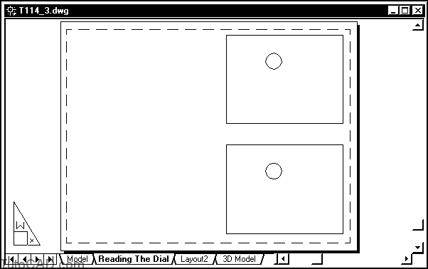
18- Select the new viewport that you copied (the viewport underneath the original viewport) to display the grips. Then right-click to invoke a shortcut & select Viewport Clip. Then pick the copied CIRCLE object inside the selected viewport as the clipping object.
You are in the process of creating a “detail” view that will show an enlarged view of the objects inside the CIRCLE on the main view.
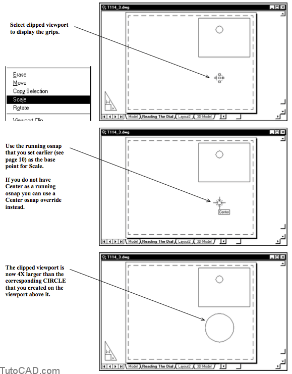
– this enlarged view will be completed by first using Scale to make the clipped viewport 4X larger
– then you will adjust the view magnification scale for the clipped viewport to be 4X larger as well (i.e. 1:1 instead of 1:4)
19- Select the clipped viewport & right-click to invoke a shortcut menu. Select Scale and then left-click on the OSNAP button in the status bar (if it is not already pushed in) and left-click for the Center osnap marker shown below as the base point. Then enter 4 as the scale.
20- Select the clipped viewport again and right-click to invoke the shortcut. Pick Display Viewport Objects & pick Yes.
21- Left-click on PAPER in the status bar to switch to MODEL.
22- Select a 1:1 viewport scale in the Viewports toolbar.
23- Left-click on MODEL in the status bar to switch to PAPER.
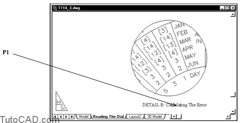
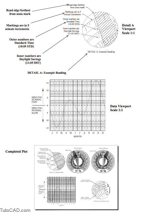
24- Pick View + Zoom + Window and pick a window so your detail view resembles the illustration below.

25- Pick Draw + Text + Single Line Text and follow the dialogue below to create a label for this detail view.
Command: _dtext
Current text style: “TIMES” Text height: 0.3750
Specify start point of text or [Justify/Style]: M ↵
Specify middle point of text: (pick near P1)
Specify height <0.3750>: 0.1 ↵
Specify rotation angle of text <0>: ↵
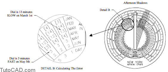
Enter text: DETAIL B: Calculating The Error ↵
Enter text: ↵
Command:
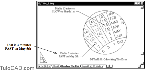
28- Pick Dimension + Leader and use the dialogue and illustrations below to add the LEADER object shown.
Command: _qleader
Specify first leader point, or [Settings]<Settings>: (turn OSNAP OFF & pick near P2)
Specify next point: (pick near P3)
Specify next point: ↵
Specify text width <0.0000>: ↵
Enter first line of annotation text <Mtext>: Dial is 13 minutes ↵
Enter next line of annotation text: SLOW on March 1st ↵
Enter next line of annotation text: ↵
Command:

27- Use a similar technique to create the other leader shown.
28- Pick View + Zoom + All to see the entire page again.
29- Pick View + Zoom + Window and pick a window so your
main view appears on screen as shown below.
30- Create the LEADER and TEXT label shown below using the same techniques as in the detail view..
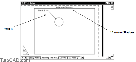
31- Select the main viewport border to display the grips and then right-click to invoke a shortcut. Select Display Viewport Objects and pick Yes.

32- Pick View + Zoom + All to display the entire page again.
More practice?
33- Add the three new viewports with the associated labels and leaders shown below (on your own) to complete this layout. You will probably have to Move or Stretch viewports that you already created so all five viewports will fit on the page.
More Practice
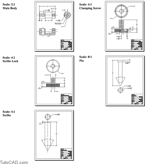
Open the T114_4.dwg drawing in your personal folder.
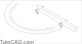
-this file already contains models for a beam compass set.
-one layout called Exploded 3D Detail shows one beam compass head in an exploded assembly.
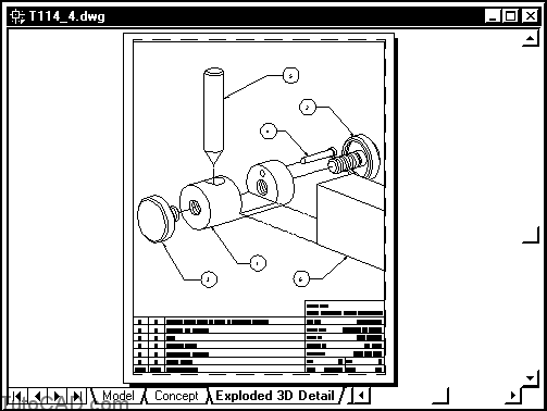
another layout called Concept explains how to use a beam compass to draw or scribe large arcs.
Your task is to create new layouts for the 2D drawings of each component in this design (5 new layouts).
– the 2D drawings already exist on the Model tab.
– use the illustrations on the next page as a guide.