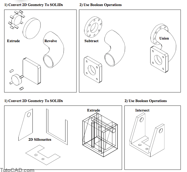
EXTRUDE, REVOLVE & Boolean Operations
In this section you will learn how to start many 3D modeling projects using 2D geometry and 5 key commands.
- you will learn how to Extrude & Revolve 2D geometry to create complex SOLID objects
- and you will learn how to use Subtract, Union & Intersect to combine SOLIDs in boolean operations.
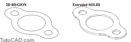
You can use Extrude to convert closed LWPOLYLINES, REGIONS, CIRCLES, ELLIPSEs and closed SPLINEs into SOLID objects.
- you are prompted to select (2D) objects and each selected object is used to generate a new individual SOLID.
- these new SOLIDs are created on the current layer which can be different than the layer(s) of the selected 2D object(s).
The 2D object(s) may be retained or deleted & you can control this with the DELOBJ system variable (which is saved in your registry).
- if DELOBJ = 1 (initial default) the original 2D objects are deleted whereas when DELOBJ = 0 these objects are retained.
Height of extrusio
You can enter a height of extrusion (default) and the extrusion direction is perpendicular to the plane of the selected 2D object(s).
- the positive extrusion direction is normally the positive Z axis of the UCS that was current when the 2D object was created.
- 3D Operations (e.g. Rotate3d) may change the orientation of 2D objects from their original orientations.
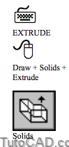
Command: EXTRUDE↵
Current wire frame density: ISOLINES=4
Select objects: (select valid 2D geometry)
Select objects: ↵
Specify height of extrusion or [Path]: (enter value for height)
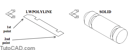
Closed LWPOLYLINEs are practical 2D object types to Extrude and you can create them directly using the Pline command
- or you can convert LINE & ARC segments (if they meet exactly end-to-end) into LWPOLYLINEs using the Join option of Pedit.
- you can also use Rectang for rectangular shapes, Polygon for polygons with equal length sides or Donut for circular shapes.
- LWPOLYLINEs must not have more than 500 vertices and segments of the same LWPOLYLINE should not cross.
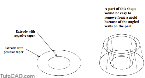
Angle of Taper
If you supply a value for the height of extrusion you will also be prompted for an angle of taper (default angle is zero).
- this feature is practical to model objects that are fabricated using molding or casting processes (i.e. draft angles).
If you attempt to use a taper angle that is too large or a height of extrusion that is too long (relative to the taper angle)
- the 2D profile may Extrude to a point before it can reach the specified height and you may get an error message.
Use positive taper angles to make the extruded profile smaller as it is extruded away from the original 2D object.
- use negative taper angles to make the extruded profile larger as it is extruded away from the original 2D object.
Command: EXTRUDE↵
Current wire frame density: ISOLINES=4
Select objects: (select approppriate 2D objects)
Select objects: ↵
Specify height of extrusion or [Path]: (supply value for height)
Specify angle of taper for extrusion <0>: (supply value for taper)
You are NOT prompted for a taper angle when you use the Path option of Extrude.
Path
You can use the Path option of Extrude instead of specifying a value for the height of extrusion.
- valid path objects include LWPOLYLINEs, LINEs, CIRCLEs, ARCs, ELLIPSEs and SPLINEs.
- the extruded SOLID starts from the plane of the 2D object and ends (perpendicular to the path) at the other path endpoint.
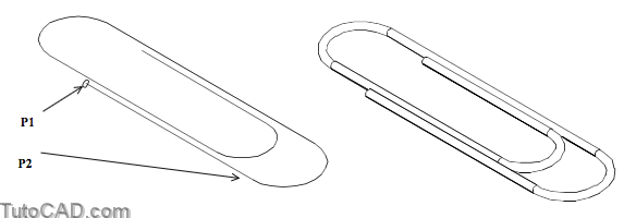
Command: EXTRUDE↵
Current wire frame density: ISOLINES=4
Select objects: (pick small CIRLCE near P1)
Select objects: ↵
Specify height of extrusion or [Path]: P↵
Select extrusion path: (pick LWPOLYLINE near P2)
Command:
The 2D profile should be perpendicular to the path at the start point or you may get unexpected results.
- if the path is a SPLINE the 2D profile is automatically rotated to be perpendicular to the path at the start point.
- otherwise, the 2D profile is projected to a plane that is perpendicular to the path and this may distort the extrusion.
The path start point should be on the 2D object plane or AutoCAD will move the path to the center of the 2D object.
Paths should change directions gradually for best results.
Planar Paths
Paths used in the Extrude command must be entirely in one plane.
- most valid paths are 2D objects and will automatically be in one plane by default.
You can use Spline to create SPLINE objects freely in 2D or 3D space, such as along a helical path for a spring.
- however, AutoCAD will not let you select a SPLINE as the path in Extrude if the desired SPLINE is not in one plane.
- for example, you could not model springs using Extrude along a helical SPLINE path (this requires Mechanical Desktop).

You can approximate 360 degrees of a helical path using 2 ARC objects where each ARC is in a different plane.
- you could then use the Path option of Extrude for a CIRCLE profile on each of these ARC paths.

- then Copy as many coils as you need and Union the individual SOLIDs together into a single SOLID spring.

The Revolve command is like using Extrude with a radial path (but you do not require a path object when you use Revolve).

- you can Revolve closed LWPOLYLINES, REGIONS, CIRCLES, ELLIPSEs and closed SPLINEs into SOLID objects.
- this command is practical for modeling objects that must be fabricated using a lathe (such as shafts).
The new SOLID object is created on the current layer which can be different than the layer of the selected 2D object(s).
- the 2D object(s) may be retained or deleted & you can control this with the DELOBJ system variable (saved in the registry).
- if DELOBJ = 1 (initial default) the original 2D object is deleted whereas when DELOBJ = 0 this object is retained.
Pick 2 points (default) to specify the axis of revolution.
- these points may even be along one edge of a closed LWPOLYLINE that you Revolve (e.g. to create a shaft).
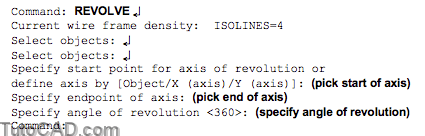
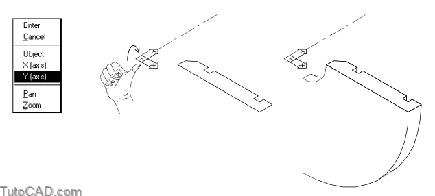
When the angle of revolution is not 360 you can use the right hand rule to determine the direction for positive rotation about an axis.
- point your right hand thumb in the direction of the specified axis and your fingers curl naturally in the positive rotation direction.
Axis Options
You could also create a LINE on the desired axis and use the Object option of Revolve to specify the axis of revolution.
- pick this LINE nearest the starting end for the axis of revolution.
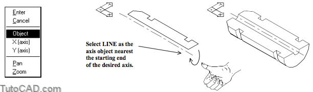
You can also invoke the X or Y options to use the X axis or Y axis of the current UCS as the axis of revolution.

Boolean Operations
You can use boolean operations to combine several SOLIDs into a single new SOLID.
- boolean operations are normally used after creating the main model features using Extrude or Revolve on 2D geometry.
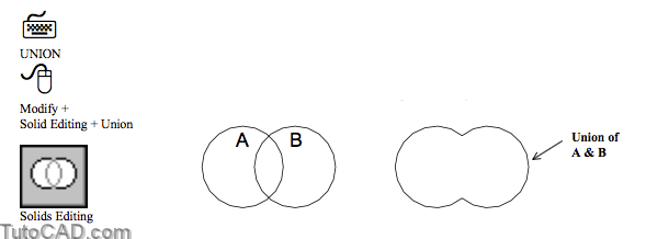
Use Union to create a new SOLID that includes the combined volumes of the selected SOLIDs (like welding parts together).
- you are prompted to select the SOLIDs to join together and you can pick as many SOLID objects as you wish.
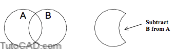
Use Subtract to remove overlapping volumes of selected SOLIDs from other SOLIDs (like milling out unwanted material).
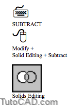
- this is a two part command in which you are first prompted to select SOLIDs that you will subtract from.
- if you select more than one SOLID to subtract from these SOLID objects are first combined together (as if you had used Union).
- then you are prompted to select SOLIDs to subtract and you can select more than one SOLID in the same operation.
Use Intersect to generate a new SOLID that includes only the common volume of the other selected SOLIDs.
- this is a powerful tool but it is not always easy to visualize.

PRACTICE USING EXTRUDE, REVOLVE & BOOLEAN OPERATIONS
» 1) Launch AutoCAD (if required). Pick File + Open and select the T304_1.dwg drawing file in your personal folder. Close all other drawings (if other drawings are open).
» 2) Pick Tools + Run Script. Select the T304.scr script file in your personal folder and pick the Open button there to run this script. This sets several system variables to match the behavior illustrated in this manual.
You will use this sketch to create a solid model.

The current drawing was created from scratch and so far there are no objects in the file.
- you will apply your new solid modeling skills and the sketch illustrated above to create a solid model for this simple part.
Three layers have already been imported into this drawing to help make your modeling task easier and they include
- construction (current layer for 2D geometry), solid (for SOLIDs) and temporary (for SOLIDs that you do not need right away).
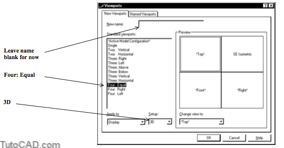
3) Pick View + Viewports + New Viewports. Select 3D as the Setup. Pick Four: Equal standard viewports. Then pick OK without entering a name for this arrangement. The lower right (Right) view should now be the current viewport.
4) Pick Draw + Circle + Center,Diameter and enter 0,0 as the center point and 6 as the diameter.
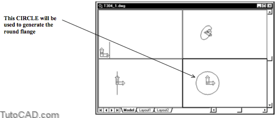
Sometimes it is easier to begin modeling projects using multiple viewports created with Vports & one of the 3D setups.
- then you can begin creating 2D geometry from any orthographic view without having to worry about the current UCS.
- later on you can return to a single viewport with an isometric view to take more advantage of the space on-screen.
»5) Turn On the POLAR, OSNAP and OTRACK buttons in the status bar (left-click on them if they are Off).
»6) Pick Draw + Circle + Center,Diameter. When AutoCAD prompts for a center point, invoke a Center osnap (without left-clicking) and hold your crosshairs over the osnap marker to acquire it as a tracking point. Move your crosshairs upward to invoke a 90 degree tooltip angle then type 2.5 and press <enter> to supply this as the center point. Enter a diameter of 0.5.

»7) Left-click in the upper right (isometric) viewport to make it the current viewport.
»8) Pick View + Viewports + 1 Viewport to return to a single viewport for the entire screen.
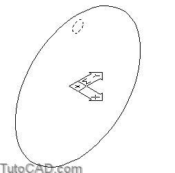
»9) Pick View + Zoom + Extents to enlarge the view of these two CIRCLEs on-screen.
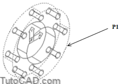
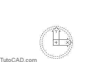
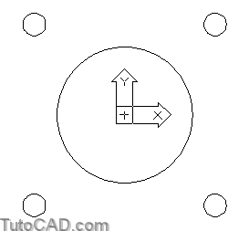
» 10) Pick Modify + 3D Operation + 3D Array. Select the small CIRCLE and press <enter> to continue.
11) Enter P to invoke the Polar option. Type 8 as the number of items in the array and press <enter> to use 360 as the angle to fill. Press <enter> to rotate as they are copied. Invoke a Center osnap for the large CIRCLE near P1 and left-click to use this as the center point of array. Then move your crosshairs near P2 to invoke a 0 degree tooltip angle and left-click to use this as the second point on axis of rotation.

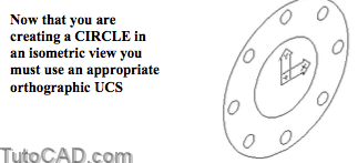
» 12) Pick Tools + Orthographic UCSs + Right.
» 13) Pick Draw + Circle + Center,Diameter. Use 0,0 as the
center point and 3 as the diameter.
14) Pick Draw + Solids + Extrude. Enter ALL then press <enter>. Enter 1 as the height. Press <enter> for 0 taper.
15) Pick Modify + Solids Editing + Subtract. Select the SOLID near P1 as the object to subtract from and press <enter>.
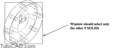
16) Use an implied window tool shown to select all other SOLIDS as the objects to subtract and press <enter>.
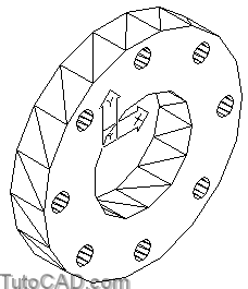
17) Pick View + Hide to make sure you subtracted the bolt holes from the main flange properly.
18) Select the new SOLID when no command is running and then pick the temporary layer in the layer control drop down list to move this object to this layer (which is off). Pick OK in the alert box and the SOLID should disappear (for now).

» 19) Pick View + 3D Views + Right.
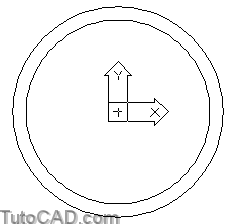
» 20) Pick Draw + Circle + Center,Diameter. Enter 0,0 as the
center point and 4 as the diameter.
» 21) Pick Modify + Offset and enter 0.25 as the distance. Select the new CIRCLE and pick a point inside as the side to offset to make a smaller CIRCLE. Press <enter> to continue.
22) Pick View + Zoom + Out to see more of the drawing area.
23) Pick Draw + Solids + Revolve. Select both CIRCLEs on
screen and press <enter> to continue.
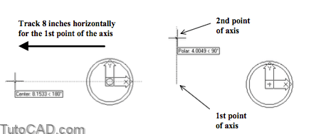
24) Hold your crosshairs over the Center osnap marker (without left-clicking) to acquire it as a tracking point. Move your crosshairs to the left to invoke a 180 tooltip angle and type 8 then press <enter> to use this as the first point of the axis. Move your crosshairs up to invoke a 90 tooltip angle then left-click to use this as the second point of the axis. Enter 90 as the angle of revolution.
25) Pick View + 3D Views + SE Isometric.
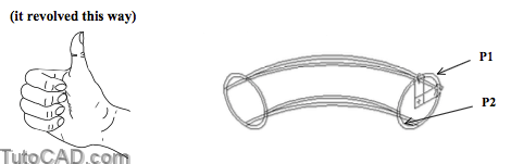
26) Pick Modify + Solids Editing + Subtract. Select the large outer SOLID near P1 as the object to subtract from then press <enter> to continue. Select the smaller inner SOLID near P2 as the object to subtract and press <enter>.
27) Pick Tools + Orthographic UCSs + Front.
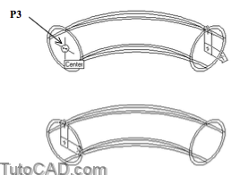
28) Pick Tools + Move UCS. Invoke a Center osnap near P3 and left-click to move the UCS to the other end of the revolved SOLID.
» 29) Select the new SOLID when no command is running and then pick the temporary layer in the layer control drop down list to move this object to this layer (which is off). Pick OK in the alert box and the SOLID should disappear (for now).
» 30) Pick View + 3D Views + Front to look at your model from the front (the same as the current UCS).
» 31) Pick Draw + Circle + Center,Diameter. Enter 0,0 as the center point and enter 3 as the diameter.
32) Pick Draw + Circle + Center,Diameter. Enter 2,2 as the center point and enter 0.5 as the diameter.

33) Pick Modify + Array. Select the Last small CIRCLE and press <enter> to continue. Enter P to invoke the Polar option. Enter 0,0 as the center point of array. Enter 4 as the number of items. Press <enter> to use 360 as the angle to fill and press <enter> to rotate as they are copied.
34) Pick Draw + Rectangle. Enter F to invoke the Fillet option and enter 0.5 as the fillet radius. Enter –3, –3 as the first corner point and 3,3 as the other corner point to create a LWPOLYLINE for the rectangular flange.

35) Pick View + Zoom + Extents.
36) Pick Draw + Region. Select all objects visible on screen and press <enter> to convert them to REGION objects.
» 37) Pick Modify + Solids Editing + Subtract. Pick the outer REGION as the object to subtract from & press <enter>. Select the circular REGIONs as the objects to subtract and press <enter> to create a new REGION (with holes in it).
» 38) Pick View + Shade + Gouraud Shaded to verify that you have indeed created a REGION with holes in it.

39) Pick Draw + Solids + Extrude. Select the new REGION and press <enter> to continue. Enter 1 as the height and press <enter> to use a taper of 0.
40) Pick View + 3D Views + SE Isometric.
41) Turn the temporary layer back On.
42) Pick Modify + Solids Editing + Union. Select all SOLIDs visible on-screen and press <enter>.
43) Select the SOLID when no command is running & pick the solid layer in the drop-down list to move it to this layer.

44)
Save the changes to your drawing and Close the file.
More practice?
» 45) Open the T304_2.dwg file in your personal folder.
» 46) Turn Off the Reference Geometry layer.
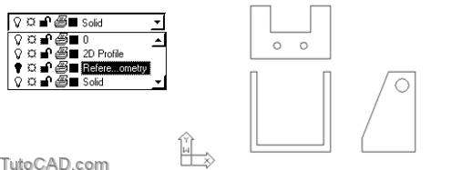
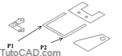
This 2D drawing of a simple bracket was modified by moving all 2D profile geometry (silhouettes) in each view to the 2D Profile layer.
- other geometry was moved to the Reference Geometry layer.
- you will use the profile geometry to create REGIONs that will beExtruded and Intersected to create a SOLID model.
» 47) Pick Modify + Polyline & use the command line historybelow to Join some LINEs into a single LWPOLYLINE.
Command: PEDIT↵
Select polyline: (pick LINE near P1)
Object selected is not a polyline
Do you want to turn it into one? <Y> Y↵
Enter an option [Close/Join/Width/Edit vertex/Fit/Spline/Decurve/Ltype gen/Undo]: J ↵Select objects: ALL↵
Select objects: ↵
4 segments added to polyline
Enter an option [Open/Join/Width/Edit vertex/Fit/Spline/Decurve/Ltype gen/Undo]: ↵
Command:
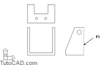
» 48) Pick Draw + Region. Select the new LWPOLYLINE that you created near P1 & the CIRCLE near P2 & press <enter>.
» 49) Pick Modify + Solids Editing + Subtract. Select the outer REGION near P1 as the object to subtract from and press <enter>. Select the circular REGION near P2 as the object to subtract and press <enter>.

50) Use a similar technique to convert the simple 2D LINEs and CIRCLEs in the other 2 views into a single REGION object in each view.
» 51) Pick View + 3D Views + SE Isometric.
» 52) Pick View + Zoom + Out.

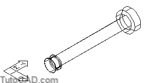
53) Pick Modify + 3D Operation + Rotate 3D & pick the REGION near P1 then press <enter>. Use Endpoint osnaps near P1 & P2 & a rotation angle of 90 degrees.
54) Pick Modify + Move. Select the rotated REGION and press <enter> to continue. Use Endpoint osnaps near P3 & P4 as the base point and second point for the move.

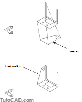
55) Pick Modify + 3D Operation + Align. Select the REGION shown below in the source location and press <enter> to continue. Use Endpoint osnaps for the source & destination points of the dashed lines illustrated below to align this REGION in 3D space as shown.
» 56) Use Extrude on each of these REGION objects with the heights of extrusion shown below.

You can use Endpoint osnaps to pick 2 points for the heights of extrusion instead of typing the desired height using your keyboard.
- AutoCAD will use the distance between the two points as the value for the height of extrusion.
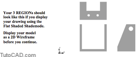
» 57) Pick Modify + Solids Editing + Intersect. Type ALL to select all three new SOLID objects and press <enter> to complete the task.
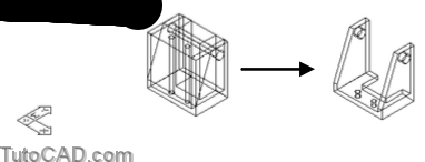
You created this complete model by Intersecting the Extruded 2D profiles (silhouettes) of each orthographic view in a 2D drawing.
- you cannot convert all 2D drawings to complete SOLID models this way but you can use this approach to start many models.
Can you do this?
» 58) Display the model using the Flat Shaded shademode and have your model revolve (orbit) continuously on screen.
» 59) Save the changes to this model and Close the file.
Still more practice?
» 60) Open the T304_3.dwg drawing in your personal folder.
» 61) Pick Modify + Polyline. Use the dialogue below to convertthese LINEs & ARCs into a single LWPOLYLINE.
Command: PEDIT↵
Select polyline: (pick LINE near P1)
Object selected is not a polyline
Do you want to turn it into one? <Y> Y↵
Enter an option [Close/Join/Width/Edit vertex/Fit/Spline/Decurve/Ltype gen/Undo]: J ↵Select objects: ALL↵
Select objects: ↵
6 segments added to polyline
Enter an option [Open/Join/Width/Edit vertex/Fit/Spline/Decurve/Ltype gen/Undo]: ↵
Command:
62) Pick View + 3D Views + SE Isometric.
63) Pick Tools + Orthographic UCS + Right.
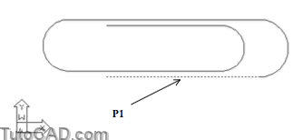
64) Pick Draw + Circle + Center,Diameter. Use an Endpoint osnap near P2 as the center point and enter 0.03 as the diameter for a circular profile.
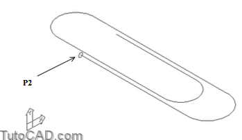
Now you are ready to Extrude this CIRCLE along the LWPOLYLINE path to create a SOLID model of a paper clip.
- the CIRCLE is perpendicular to this path.
65) Pick Draw + Solid + Extrude. Select the CIRCLE and press <enter> to continue. Invoke the Path option and select the LWPOLYLINE as the path.
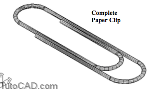
66) Save the changes to your paper clip and Close the file.
Still more practice?
67) Open the T304_4.dwg drawing in your personal folder.
68) Pick the Model tab to switch to the model.
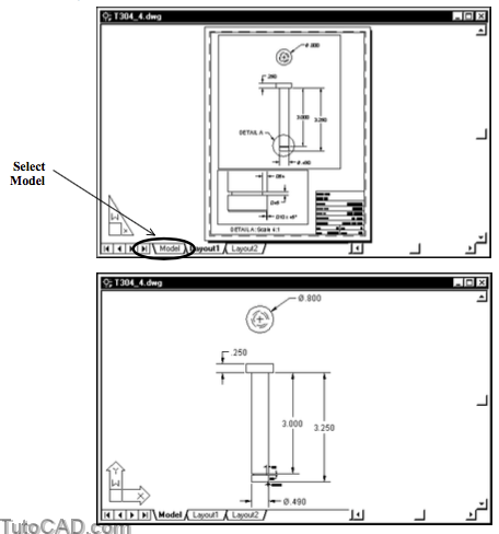
» 69) Turn Off the Dimension and Dimension – Detail layers.
» 70) Pick Draw + Line and use Midpoint osnaps to draw a LINE down the center line of the pin in this 2D drawing. You may have to Zoom In to select the Midpoint of the bottom edge because there is a small chamfer that creates two LINEs.
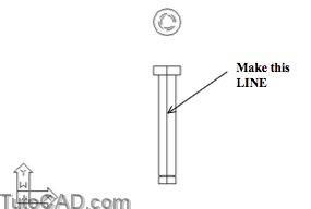
71) Use Trim and Erase to reduce the visible geometry to one half of the pin profile. You may have to Zoom In to see all of the small LINEs (especially at the bottom of the pin).
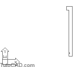
Convert the LINEs on-screen into a single LWPOLYLINE using the Pedit command.
Revolve the LWPOLYLINE about the edge that corresponds to the center line for the pin.
Pick View + 3D Views + SE Isometric.
75) Save the changes to this model and Close the file.