FILLET, CHAMFER & SLICE in a 3D drawing
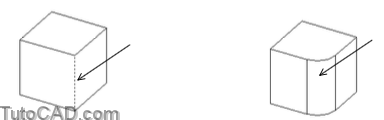
AutoCAD offers different options when you use Fillet on SOLIDs compared to when you use Fillet on 2D objects.
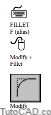
- if you select a SOLID at the first prompt AutoCAD highlights the selected edge and lets you specify a new radius.
- you can press <enter> to terminate the Fillet command if you want to fillet only the one selected edge.
You can continue to select more edges and you can change the radius for these other edges in the same Fillet command.
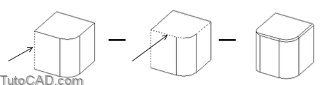
- use the chain option to select an entire collection of edges that meet tangentially end-to-end (instead of one edge at a time)
- the following illustrations & command line history demonstrate how you can use different options in the same Fillet command.
Command: FILLET↵
Current settings: Mode = TRIM, Radius = 1.000
Select first object or [Polyline/Radius/Trim]: (picksingleedgenearP1)
Enter fillet radius <1.000>: 0.5↵
Select an edge or [Chain/Radius]: C↵
Select an edge chain or [Edge/Radius]: R↵
Enter fillet radius <0.5000>: 0.1↵
Select an edge chain or [Edge/Radius]: (pick tangential edge near P2)
Select an edge chain or [Edge/Radius]: ↵
4 edge(s) selected for fillet.
Command:
Unless the desired fillet is a key feature in your model you should delay using Fillet on SOLIDs for as long as possible.
- when you Fillet edges you lose osnap targets (e.g. Intersection) that could be helpful for completing the model.
- you might even omit very small Fillet radii entirely to keep SOLID models simple (include this information in 2D drawings instead).
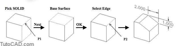
Chamfer prompts are different when you select SOLIDs compared to when you use Chamfer on LINEs.
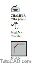
- AutoCAD recognizes that you have selected a SOLID when you select a SOLID edge at the first prompt to select first line.
- an adjacent face of the selected edge is highlighted & you can accept it as the base surface by pressing <enter> for <OK>.
- if you invoke Next the next adjacent face is highlighted as the base surface and you can press <enter> to accept that face.
After you establish which surface is the base surface you can select several individual edges to chamfer relative to this surface.
- the Loop option selects all edges around the base surface.
Command: CHAMFER↵
(TRIM mode) Current chamfer Dist1 = 0.5000, Dist2 = 0.5000
Select first line or [Polyline/Distance/Angle/Trim/Method]: (pickSOLIDedgenearP1)
Base surface selection…
Enter surface selection option [Next/OK (current)] <OK>: N ↵
Enter surface selection option [Next/OK (current)] <OK>: ↵
Specify base surface chamfer distance <0.5000>: 2 ↵
Specify other surface chamfer distance <0.5000>: 1 ↵
Select an edge or [Loop]: (pickedgenearP2again)
Select an edge or [Loop]: ↵
Command:
You can Slice SOLIDs with a specified plane and keep one or both sides (it is like cutting the SOLID with an infinitely thin knife).

Use three points (default) to specify the desired plane or use predefined planes relative to the current UCS, a view or an object.
- for example, you could use a plane that is parallel to the XY plane of the current UCS and passes through a specified point.
AutoCAD prompts you to select a point on the side (of the plane) you wish to keep once you have specified the slicing plane
- or you can invoke the Both option if you need both sides.
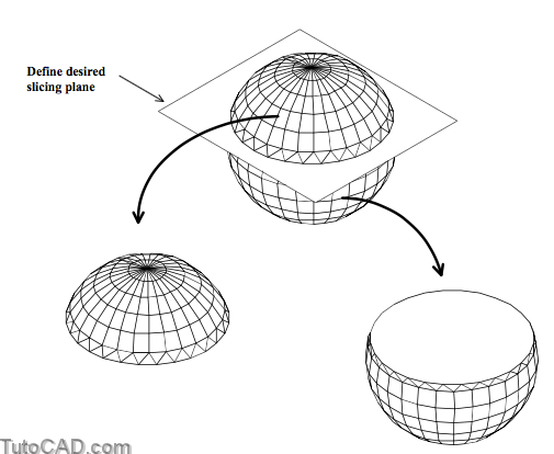
Command: SLICE↵
Select objects: (pick SOLID)
Select objects: ↵
Specify first point on slicing plane by [Object/Zaxis/View/XY/YZ/ZX/3points] <3points>: XY↵
Specify a point on the XY-plane <0,0,0>: (pick point on desired plane)
Specify a point on desired side of the plane or [keep Both sides]: (pickpointoruseBoth) Command:
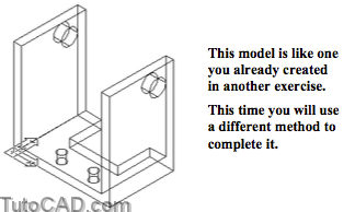
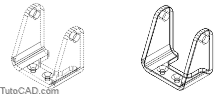
PRACTICE WITH FILLET, CHAMFER & SLICE
» 1) Close the drawing from the previous exercise if it is open.
» 2) Open the T304_6.dwg file in your personal folder.
3) Pick Modify + Chamfer. Select the top edge near P1. If the front face is highlighted as shown below press <enter> to accept this surface as the base surface. (otherwise invoke Next so this face is highlighted and then press <enter>). The command line history is shown. Enter 2.5 as the first distance and 1.0 as the second distance. (You will be prompted to select edges in the next step)
Command: CHAMFER↵
(TRIM mode) Current chamfer Dist1 = 0.5000, Dist2 = 0.5000
Select first line or [Polyline/Distance/Angle/Trim/Method]: (pickshortedgenearP1)
Base surface selection…
Enter surface selection option [Next/OK (current)] <OK>: (acceptfrontface)
Specify base surface chamfer distance <0.5000>: 2.5 ↵
Specify other surface chamfer distance <0.5000>: 1.0 ↵

4) Pick the two edges shown highlighted near P1 and P2 and press <enter> to apply the chamfer.

5) Pick View + 3D Orbit. Drag the model a small amount so that you can see all edges distinctly (they should not overlap) from the new viewing direction. Then press <Esc> to terminate 3dorbit.
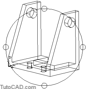
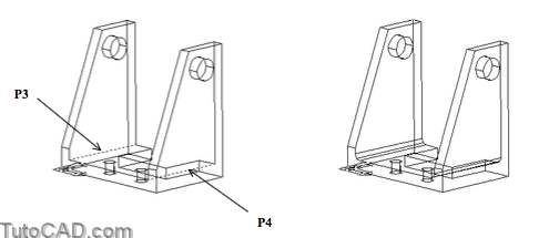
6) Pick Modify + Fillet. Select the edge shown highlighted near P3 and enter a new radius of 0.125. Then select another edge shown highlighted near P4 and press <enter> to complete the task.
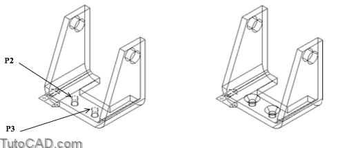
7) Use a similar technique to Fillet the outer edges shown highlighted below (the same corners) with a 0.375 radius.
More practice?
8) Invoke the Previous option of Zoom.
9) Pick Modify + Chamfer and select the edge of one of the small holes near P1. Accept the face shown highlighted below as the base surface to continue.

10) Enter 0.1425 as the distance along both surfaces and then pick the top edges of both small holes near P2 and P3 to countersink these holes.
Why 0.1425?
For a 90 degree countersink angle this distance (0.1425) is half the difference between the large (0.55) countersink and small diameter (0.265) hole.
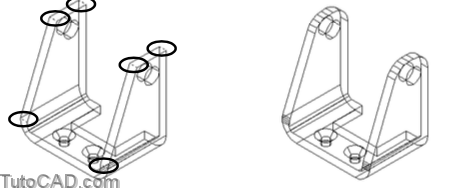
11) Apply a Fillet of 0.5 radius to the 6 highlighted edges shown.
12) Apply a Fillet of 0.25 radius to the 4 highlighted edges.

13) Now there are two chains of edges that meet end-to-end tangentially around the part. Invoke Fillet & select any edge. Then use the Chain option of Fillet to select all edges shown highlighted below for a fillet radius of 0.03.
14) Pick View + Shade + Gouraud Shaded.
15) Pick View + 3D Orbit. Right-click in the drawing area to invoke a shortcut. Pick More then pick Continuous Orbit. Drag your model into an orbit and enjoy watching your finished model revolve on-screen. Press <Esc> when you are ready to continue.
Still more practice?
16) Save the changes to your drawing and Close the file.
17) Start a New drawing from Scratch using English defaults.
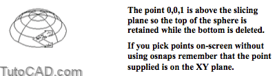
18) Pick Draw + Solids + Sphere. Press <enter> to use the origin <0,0,0> as the center point. Invoke Diameter and enter a diameter of 2.25.
19) Pick View + 3D Views + SE Isometric.
20) Pick Draw + Solids + Slice. Select the sphere and press <enter> to continue. Follow the command line history below to create the top part of a sphere shown.
Command: SLICE↵
Select objects: (pickthesphere)
Select objects: ↵
Specify first point on slicing plane by [Object/Zaxis/View/XY/YZ/ZX/3points] <3points>: XY↵
Specify a point on the XY-plane <0,0,0>: 0,0,0.375 ↵
Specify a point on desired side of the plane or [keep Both sides]: 0,0,1 ↵
Command:
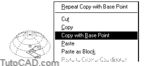
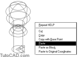
21) Select the sphere when no command is running to highlight this SOLID. Right-click in the drawing area to invoke a shortcut and pick Copy with base point. Enter 0,0,0 as the base point and then press <Esc> twice to clear the grips.
22) Open the T304_7.dwg file in your personal folder.
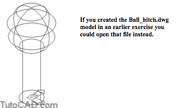
23) Right-click in the drawing area to invoke a shortcut and pick Paste. Enter 0,0,2.125 as the insertion point.
24) Pick Modify + Solids Editing + Union. Select the main model (red) first and then select the sliced sphere & press <enter> create a new SOLID. Pick View + Hide.

» 25) Save the changes to the current drawing and Close the file. » 26) Close the drawing (unnamed) that still contains the sliced
sphere without giving it a name or saving the changes.

You can create simple SOLIDs in unnamed drawings then copy and paste them into your real models using this technique.
- you can experiment outside your model files in these temporary scratch pad drawing files.
- be sure to use Copy with base point so you can be precise when you Paste it into another drawing.
- this is also a practical technique for importing several SOLIDs in individual part files into a single assembly file.
You selected the main model first before selecting the pasted solid (on layer 0) when you used Union
- this placed the new unioned SOLID on the same layer as the main model (instead of layer 0).