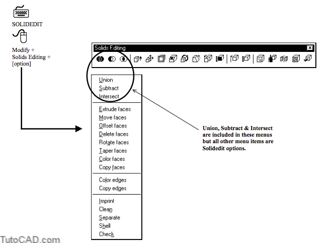
Introduction To SOLIDEDIT
This section introduces the 15 options of the Solidedit command.
- you can invoke the desired option directly from the Modify + Solids Editing pulldown menu or the Solids Editing toolbar.
Overview
Three main option categories of Solidedit are Face, Edge & Body.
Command: SOLIDEDIT↵
Solids editing automatic checking: SOLIDCHECK=1
Enter a solids editing option [Face/Edge/Body/Undo/eXit] <eXit>: (invoke an option)
Most Face options let you change the shape of SOLIDs using the Extrude, Move, Offset, Delete, Rotate & Taper sub-options
- you can also copy faces & change their color.
Edge options let you copy or change the color of SOLID edges.
Body options let you create SOLID shells, imprint 2D geometry on faces, clean redundant information and separate & check SOLIDs.
Selecting Faces
You must select faces when you use Solidedit Face options.
- you can pick an isoline or edge on the desired face(s) or pick inside the desired face(s) with your pick box.

You can also use Cpolygon, Crossing or Fence tools to select the desired face(s).
When you have selected one or more faces you can then use the ALL option to select all faces if you wish
- and you can continue to add more faces to the selection set or use Remove to remove specific faces from the selection set.
Extrude Faces is like using Extrude on a 2D profile.
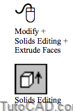
- you enter a height perpendicular to the face (or extrude along a path) and you can specify an optional taper angle.
Move Faces is like using the Move command.
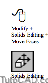
- you are prompted for a base point or displacement and you can enter a second point of displacement.
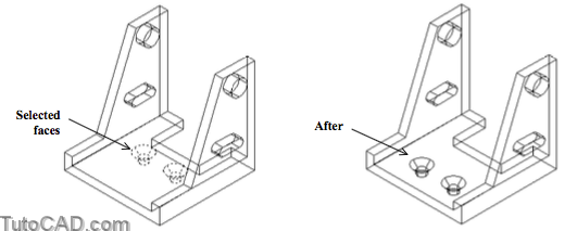
Delete Faces is like using Erase.
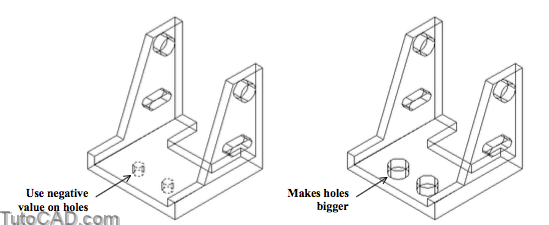
Offset Faces in a positive direction to make a selected face move perpendicular to the face such that there is more material
- for example, if you offset the surface of a hole by a positive value the hole becomes smaller (more material).
- you must offset a hole surface by a negative amount to make the hole bigger.

Rotate Faces in the same way as you use Rotate3d.
- select the desired faces to rotate then specify the axis of rotation and rotation angle.
- you can use the right hand rule to remember the direction of positive rotation about the axis.

Taper Faces lets you apply a taper (draft) angle on faces for a specified direction.
- you define the direction by picking two points and then you enter the taper angle.
- positive taper angles normally reduces the amount of material as a face is tapered along the specified direction.

Shell transforms the selected SOLID into a shell and is ideal for modeling containers & component housings (e.g consumer goods).
- create a model of the inside or outside of the desired shape then turn the (filled) SOLID into a SOLID shell.
Use positive values for the shell offset distance if your original SOLID represents the outside of the desired shell.
- otherwise use a negative value for the shell offset distance.

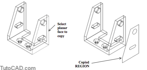
Copy Faces lets you copy selected faces a specified distance from the original faces using a base point and second point.
- for example, you could copy a complex planar face (that requires a matching gasket) to generate a REGION.
- then you could Extrude the new REGION into a SOLID gasket.
If a face is in one plane the copied object is a REGION whereas curved faces are copied as BODY objects.
- use AutoCAD Help to learn more about BODY objects.
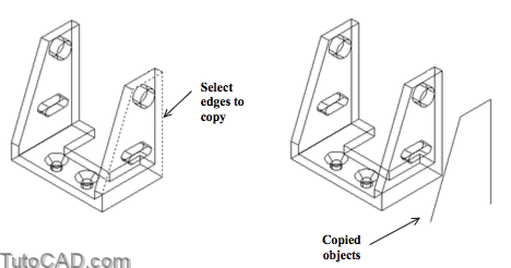
Copy Edges lets you copy selected edges at a specified distance from the original edges using a base point and second point.
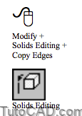
- new objects are LINEs, ARCs, CIRCLEs, ELLIPSEs or SPLINEs.
- you could use these copied 2D objects to begin new parts that must mate with the original SOLID.
Color Faces lets you change the AutoCAD Color Index of selected faces to change how SOLIDs are shaded or rendered.

- normally the color of all SOLID faces are the same as the color assigned to the SOLID and this is normally BYLAYER.
- however, for presentation purposes you may want to highlight some faces by having them render with a different color.
- you may even assign different materials BYCOLOR for rendering later (e.g. apply a knurl texture to part of a shaft).
Color Edges lets you change the AutoCAD Color Index of selected edges to change how SOLIDs are displayed & plotted.
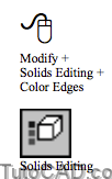
- normally the color of all SOLID edges are the same as the color assigned to the SOLID and this is normally BYLAYER.
- however, for presentation purposes you may want to highlight some edges by having them display or Plot with a different color.
- for example, if you use color dependent plot styles you could assign a different lineweight to some edges using this feature.
Imprint lets you incorporate 2D objects on SOLID faces.
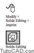
- for example, you could imprint construction geometry on SOLID faces to help you add new SOLID features to a model later on.
- Move a SOLID & imprinted 2D geometry is moved with it.

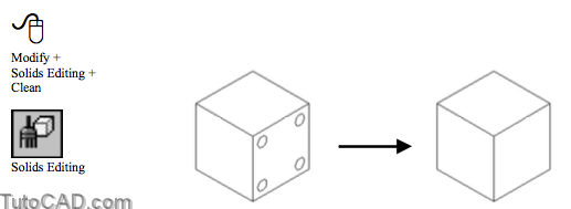
- Clean will delete all imprinted 2D geometry on SOLIDs and any other redundant information that is not required by the SOLID.
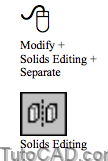
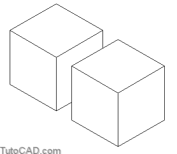
Separate breaks down SOLIDs with disjointed volumes into independent SOLIDs.
- you CANNOT use Separate to reverse boolean operations (e.g. to recover a cylindrical SOLID used to make a hole).
For example, you could Union two box SOLIDs shown below even though they do not share any common volume.
- the resulting SOLID would be one object but you could use the Separate option to convert it back into two SOLIDs again.
- you would not be able to Separate them using this option if they shared any common volume.
Check is used to verify that a SOLID is a valid ACIS solid and is independent of the SOLIDCHECK system variable.
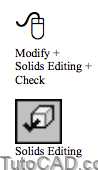
- AutoCAD also verifies each edit that you perform on SOLIDs automatically if the SOLIDCHECK variable is 1 (default).
You may attempt to modify SOLIDs with Solidedit such that the end result would no longer be a valid SOLID.
- this normally results in an error message and the SOLID remains in the same state it was before using Solidedit.
PRACTICE WORKING WITH SOLIDEDIT
»1) Close the drawing from the previous exercise if it is open.
»2) Open the T304_8.dwg drawing from your personal folder.
»3) Pick Modify + Solids Editing + Extrude Faces. Select the edge near P1 to highlight the 2 adjacent faces as shown.
Command: SOLIDEDIT↵
Solids editing automatic checking: SOLIDCHECK=1
Enter a solids editing option [Face/Edge/Body/Undo/eXit] <eXit>: _face
Enter a face editing option [Extrude/Move/Rotate/Offset/Taper/Delete/Copy/coLor/Undo/eXit] <eXit>: _extrude Select faces or [Undo/Remove]: (pick edge near P1)
2 faces found.

4) Enter R to invoke the Remove option and select the edge near P2 to remove the upper face from the selection set.
Select faces or [Undo/Remove/ALL]: R↵
Remove faces or [Undo/Add/ALL]: (picktheedgenearP2)
2 faces found, 1 removed.

You do not have to explicitly invoke the Remove option to remove faces from the selection set of faces.
- press & hold the <Shift> key while you select an edge (at the prompt to add faces) to remove selected faces from the set.
5) Press <enter> to continue and enter 1 as the height. Press <enter> to use a taper angle of zero & <enter> twice to terminate Solidedit.
Remove faces or [Undo/Add/ALL]: ↵
Specify height of extrusion or [Path]: 1 ↵
Specify angle of taper for extrusion <0>: ↵
Solid validation started.
Solid validation completed.
Enter a face editing option [Extrude/Move/Rotate/Offset/Taper/Delete/Copy/coLor/Undo/eXit] <eXit>: ↵
Solids editing automatic checking: SOLIDCHECK=1
Enter a solids editing option [Face/Edge/Body/Undo/eXit] <eXit>: ↵
Command:
You must explicitly <eXit> Solidedit when you are finished using the desired option even if you invoke this option from a menu.
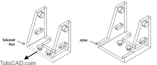
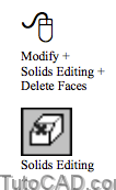
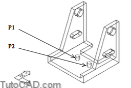
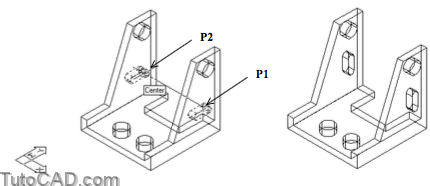
6) Pick Modify + Solids Editing + Delete Faces. Select the isolines on countersunk faces near P1 and P2 (you may have to Zoom In to select them). Then press <enter> three times to terminate Solidedit.

» 7) Make sure the POLAR & OSNAP status bar buttons are On.
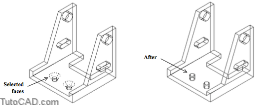
» 8) Pick Modify + Solids Editing + Move Faces. Select the two holes by selecting isolines on the curved faces near P1 and P2 (you may have to Zoom In to select them). Press <enter> to continue.
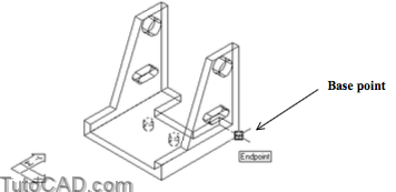
9) Left-click with the Endpoint osnap shown below as the base point for the move.
10) Move your crosshairs down and to the left to invoke a 270 degree tooltip angle. Type 0.75 as the distance and press <enter> to use this as the second point of displacement. Press <enter> twice to terminate Solidedit.

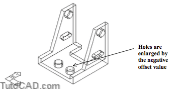
» 11) Pick Modify + Solids Editing + Offset Faces. Select the same faces (the cylindrical faces of the small holes) as in the last step and press <enter> to continue. Enter negative 0.125 as the offset distance and press <enter> twice to terminate Solidedit.
12) Pick Modify + Solid Editing + Rotate Faces. Select the faces of slotted holes shown below (you may want to Zoom in) and press <enter> to continue. You must select two faces for each slot and you can select them by selecting appropriate isolines.

13) Use Center osnaps to specify the axis of rotation near P1 and P2 (in that order) and enter 90 as the rotation angle. Press <enter> twice to terminate Solidedit.
More practice?
14) Save the changes to the current drawing and Close the file.
15) Open the T304_9.dwg drawing in your personal folder.
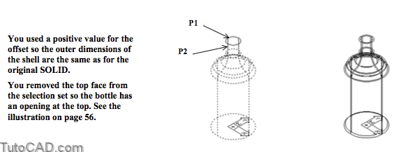
16) Pick Modify + Solids Editing + Shell. Select the top edge of this SOLID bottle near P1 to select the entire model. You will then be automatically prompted to Remove faces. Pick the same edge near P2 to remove the top face and the short cylindrical surface for the top of the bottle.
Command: SOLIDEDIT↵
Solids editing automatic checking: SOLIDCHECK=1
Enter a solids editing option [Face/Edge/Body/Undo/eXit] <eXit>: _body
Enter a body editing option
[Imprint/seParate solids/Shell/cLean/Check/Undo/eXit] <eXit>: _shell Select a 3D solid: (pick top circular edge near P1)
Remove faces or [Undo/Add/ALL]: (pick same edge near P1 again)
2 faces found, 2 removed.
» 17) Press & hold <Shift> while you select the cylindrical face on the isoline near P2 (to add it back into the selection set). Press <enter> to continue and enter 0.1 as the offset distance. Press <enter> twice to terminate Solidedit.
Remove faces or [Undo/Add/ALL]: (press <SHIFT> while you select isoline near P2)
1 face found.
Remove faces or [Undo/Add/ALL]: ↵
Enter the shell offset distance: 0.1↵
Solid validation started.
Solid validation completed.
Enter a body editing option
[Imprint/seParate solids/Shell/cLean/Check/Undo/eXit] <eXit>: ↵
Solids editing automatic checking: SOLIDCHECK=1
Enter a solids editing option [Face/Edge/Body/Undo/eXit] <eXit>: ↵
Command:
18) Save the changes to this drawing and Close the file.