Generating 2D Drawings From SOLIDs – Process Overview
Once you have created a SOLID model in AutoCAD 2000 you can use tools to generate 2D drawings (i.e. a Layout ready to Plot).
- these tools demand more effort than the relatively automatic process used in Mechanical Desktop
- and these layouts are NOT automatically linked to the SOLID model (i.e. models & drawings are not associative).
- however, you can use these tools on SOLIDs to generate traditional 2D drawings that satisfy specific drafting standards.
First Create The SOLID Model

You must make special viewports in a Layout using Solview (you will probably also want a title block on this layout).
- for example, you could make Top, Front & Right viewports.

When you define these special viewports with Solview it is like unfolding a glass box with projections of views on each face.
- Solview does NOT generate objects that will eventually appear in these viewports on the finished 2D Layout.
- Solview defines viewing directions, creates special layers, defines viewport sizes & sets drawing (view magnification) scale.

You can use Soldraw to automatically create 2D geometry in each viewport AFTER creating these special viewports with Solview.

- 2D geometry representing hidden lines is placed on a different layer than 2D geometry that represents visible lines.
- there is a separate set of layers for each viewport and these sets of layers only appear in the appropriate viewport.

You must manually create dimensions for each view as you normally would when you make 2D drawings.
- you create dimensions from the Layout tab but these dimension objects are in the model (MODEL is displayed in the status bar).
- dimensions should be created on an appropriate layer in each view (the dimension layers created by Solview).
You Plot 2D drawings from the Layout tab.
- change layer settings for the viewport layer (VPORTS) so that viewport borders are not included in the plot.

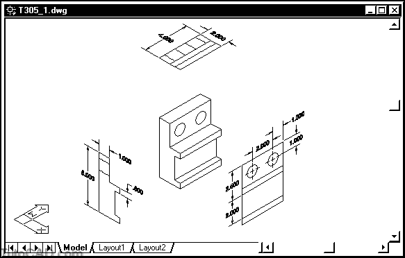
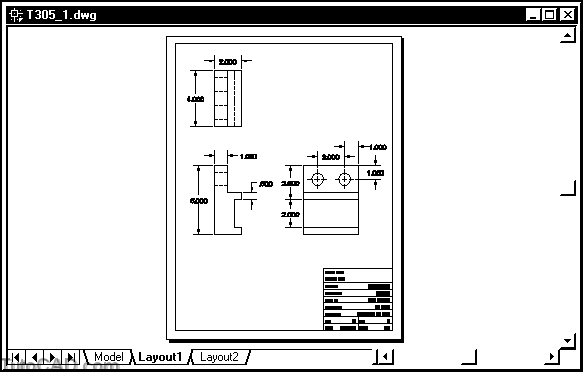
You will investigate the simple drawing illustrated above (it has already been set up) in the next exercise.
- then you will be ready to start generating your own 2D drawings from SOLIDs in the rest of this document.
PRACTICE WITH A COMPLETED DRAWING
» 1)Launch AutoCAD (if required). Pick File + Open and select the T305_1.dwg drawing file in your personal folder. Close all other drawings (if other drawings are open).
» 2) Pick Tools + Run Script. Select the T305.scr script file in your personal folder and pick the Open button there to run this script. This sets several system variables to match the behavior illustrated in this manual.
3) Left-click on the Layout1 tab to switch to this layout.
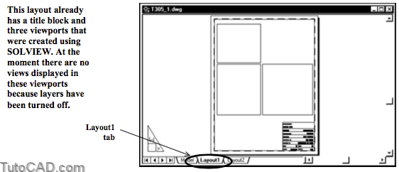
This layout has already been set up using Pagesetup
- the plot scale is normally set up as 1:1 for all drawing scales
- display magnification scale is set according to the desired drawing scale for each viewport.
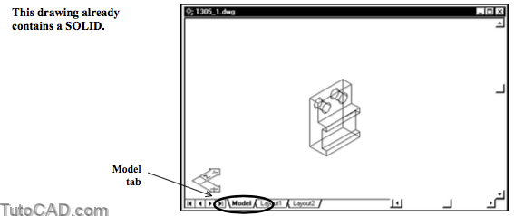
» 4) Left-click on the Model tab (not MODEL in the status bar) to return to the model again.
» 5) Pick Format + Layer. Left-click on the light bulb icons for the layers indicated below to toggle these layers On. Then pick OK to continue.
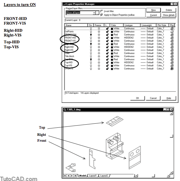
The *HID layers use a HIDDEN2 linetype and contain 2D objects that represent hidden lines in each view
- whereas *VIS layers use a continuous linetype and contain objects that represent visible lines in each view.
- each view also has a *DIM layer that is reserved for you to create dimensions on.
6) Pick Format + Layer and turn the remaining *DIM layers On. Then pick OK to continue.
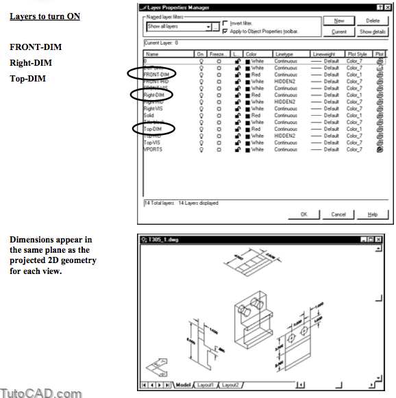
Soldraw automatically creates 2D geometry on *HID & *VIS layers
- but you must create your own dimensions manually on the appropriate *DIM layer on the layout tab.
When you change current viewports the current UCS changes automatically to the appropriate plane of the projected view.
- so when you add dimensions they are automatically created in the correct plane.
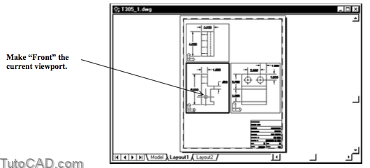
» 7) Left-click on the Layout1 tab again.
» 8) Double-click in the Front viewport to make it current.
9) Pick Format + Layer. Observe the layer settings for this viewport and pick OK.
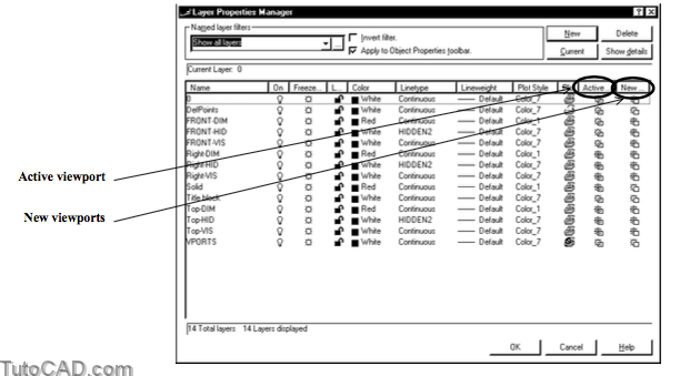
The active (front) viewport has layers frozen in this specific viewport
- Right-*, Top-* & Solid layers do not display in the Front view.
- The Right-*, Top-* and Front-* layers are also automatically frozen in New viewports.
- objects on these layers are visible only in appropriate viewports.
10) Right-click on the Layout1 tab to invoke a shortcut and select Page Setup. On the Plot Device tab select the HP LaserJet.pc3 (or equivalent) plot device. Then pick the Layout Settings tab to continue.
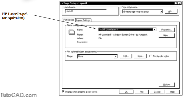
11) Verify that your settings match those below and pick OK.

You can change the Page Setup at any time using this approach. – initially this Layout had None as the Plot Device so you had to select an actual device before you Preview the plot.
12) Pick File + Plot Preview. Observe the preview then press <esc> to terminate Preview.
You have briefly examined a 2D drawing that was already set up and created using Solview & Soldraw utilities.
in the remainder of this document you will learn how to use these tools to create your own 2D drawings from SOLIDs.
» 13) Save the changes to this drawing and Close the file.