Standard SOLID Primitives in a 3D drawing
You can generate all six SOLID shapes illustrated on this page by creating appropriate 2D geometry & then using Extrude or Revolve.
- but you can also create these SOLID primitives using an AutoCAD command of the same name as the desired primitive.
- this approach lets you create simple SOLIDs directly without having to sketch 2D profiles that must be extruded or revolved.
- for example, you can use Cylinder to create a SOLID that will be Subtracted from other SOLIDs (e.g. to create a bolt hole).
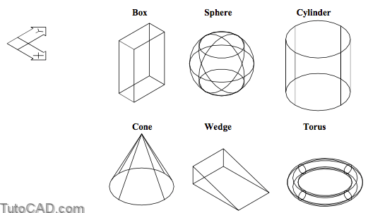
These SOLID primitives are created relative to the UCS XY plane shown in the above orientations.
- this means you must orient your UCS to an appropriate plane before you use these commands to make the primitives
- or you could create primitives in any orientation and use 3D operations (e.g. Align) to change their orientations later.
When you create some of these primitives you can temporarily use a different direction for the Z axis without having to change your UCS.
- for example, you can create a Cylinder on any axis, not just one that is perpendicular (default) to the XY plane of the current UCS.
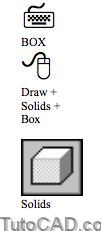
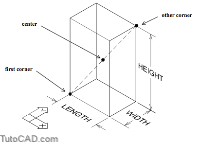
Use Box to create a boxed shape solid with one face parallel to the XY plane of the current UCS.
- you can specify the box dimensions in a variety of ways but by default you are prompted for two opposite corners of the box.
– you can also invoke the CEnter option at the first prompt to pick the center point first instead of the first corner.

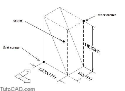
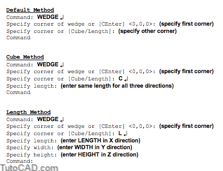
Use Wedge to create half of one Box with one face parallel to the XY plane of the current UCS.
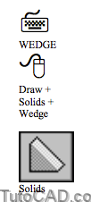
- you could Union two Wedges together to create a Box.
- the command syntax for Wedge is identical to Box (compare dialogue below with previous page).
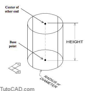
You can use Cylinder to create cylindrical SOLIDs (which is ideal for Subtracting bolt holes in mechanical parts).

- you can specify the diameter or radius (default) in the same way as you would when you use Circle in 2D geometry.
- you can also invoke the Elliptical option to generate elliptical cylinders but this shape is impractical for most models.
Command: CYLINDER↵
Current wire frame density: ISOLINES=4
Specify center point for base of cylinder or [Elliptical] <0,0,0>: (pickbasepoint)
Specify radius for base of cylinder or [Diameter]: (enterradiusorinvokeDiameteroption) Specify height of cylinder or [Center of other end]: (enter height)
Command:
If you specify a height (default) the cylindrical SOLID will always be parallel to the Z axis of the current UCS
- but you can invoke the Center of other end option to specify the other end of the cylinder instead of specifying a height.
- this lets you create cylindrical SOLIDs along any axis without having to change your UCS first.
- the height of the cylindrical SOLID is implied by the distance between the first point and the other end of the cylinder.
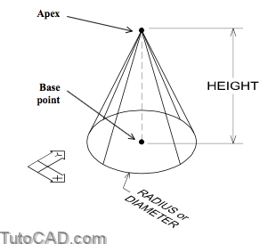
Use Cone to create a conical SOLID (which is ideal for creating countersunk holes as illustrated below).
You will find that the command syntax for Cone is similar to that for Cylinder (compare dialogue below with the previous page).
- for example, you can also create Elliptical shaped Cones
- and you can use the Apex option to specify the other end of the cone (compares with Center of other end option of Cylinder).
Command: CONE↵
Current wire frame density: ISOLINES=4
Specify center point for base of cone or [Elliptical] <0,0,0>: (pickbasepoint)
Specify radius for base of cone or [Diameter]: (enterradiusorinvokeDiameteroption) Specify height of cone or [Apex]: (enterheightorinvokeApexoption)
Command:

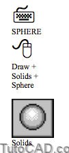
Use Sphere to create spherical SOLIDs.
- you specify the center point and then you can enter a radius (default) or invoke the Diameter option to specify a diameter.
You can snap to the center of a spherical SOLID (or portions of one) using the Center osnap.
- select one of the circular isolines to invoke a Center osnap.
- it does not matter whether the center of the circular isoline actually coincides with the spherical SOLID center point.
The current value of ISOLINES determines how many circular isolines are displayed on a spherical SOLID (like all other SOLIDs)
- many commands that create SOLIDs report the current value of ISOLINES at the command line when you invoke the command.
- you can change the appearance of all SOLIDs (even after you create them) by changing the ISOLINES system variable.
Command: SPHERE↵
Current wire frame density: ISOLINES=4
Specify center of sphere <0,0,0>: (pick center point)
Specify radius of sphere or [Diameter]: (enter radius or invoke Diameter)
Command:

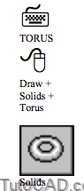
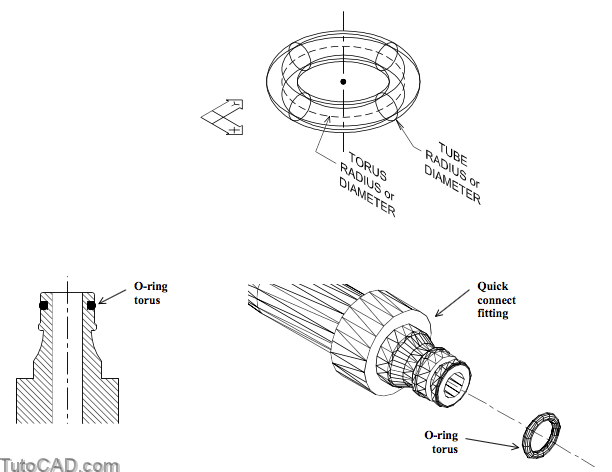
Use Torus to create a SOLID torus with an axis parallel to the Z axis of the current UCS.
- this primitive is ideal for creating o-rings or similar SOLIDs.
There are two radii to consider when you create a torus SOLID and it helps to imagine revolving a CIRCLE about the torus axis.
- the torus radius corresponds to the radius of the path that a CIRCLE profile could be revolved along (about the torus axis).
- the tube radius corresponds to the radius of the CIRCLE profile that is revolved about the torus axis.
- you can specify the radii (default) or invoke the Diameter option to specify diameters if this is more convenient.
Command: TORUS↵
Current wire frame density: ISOLINES=4
Specify center of torus <0,0,0>: (pick center point)
Specify radius of torus or [Diameter]: (enter the TORUS radius or invoke Diameter)
Specify radius of tube or [Diameter]: (enter the TUBE radius or invoke Diameter)
Command:
PRACTICE CREATING MODELS USING ONLY PRIMITIVE SOLIDS
»1) Close the drawing from the previous exercise if it is open.
»2) Start a New drawing from Scratch using English defaults.
»3) Create a new red Layer called Solid and make it current.
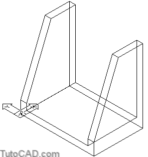
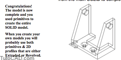
In this exercise you will create a SOLID model illustrated in this sketch using only SOLID primitives.
Compare this approach with the method used in the exercise starting on page 20.
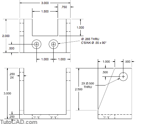
4) Pick Draw + Solids + Box. Press <enter> to start the box at the origin <0,0,0>. Enter L to invoke the Length option then enter 3 as the length, 2 as the width and 3 as the height. The command line history is shown below.
Command: BOX↵
corner of box or [CEnter] <0,0,0>: ↵
corner or [Cube/Length]: L ↵
Specify length: 3↵
Specify width: 2↵
Specify height: 3↵
Command
5) Pick View + 3D Views + SE Isometric to see an isometric view of the new box.
6) Pick Draw + Solids + Box again. Press <enter> to start the box at the origin <0,0,0>. Enter L to invoke the Length option, 2.5 as the length, 2 as the width & 2.75 as the height.

7) Pick Modify + Move. Enter L to select the Last SOLID and press <enter> to continue. Use a Midpoint osnaps shown for the basepoint and the second point.
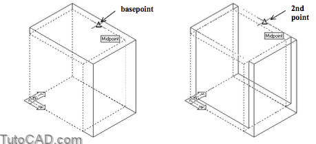
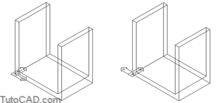
8) Pick Modify + Solids Editing + Subtract. Select the large box as the object to subtract from then press <enter> to continue. Select the small box as the object to subtract and press <enter> to complete the task.

9) PickTools+NewUCS+Zandenter90torotatetheUCS about the Z axis by 90 degrees.
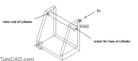
10) Pick Draw + Solids + Wedge. Use an Endpoint osnap near P1 as the first corner. Enter L to invoke the Length option and enter 1 as the length, negative 3 as the width and negative 2.5 as the height.
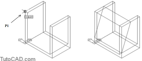
11) Pick Modify + Solids Editing + Subtract. Subtract the wedge from the main SOLID.
12) Pick Tools + New UCS + World.
13) Pick Draw + Solids + Cylinder. Invoke the From osnap and follow the dialogue below to create a cylindrical SOLID for a hole. Note that you are able to create a cylinder that is not perpendicular to the XY plane of the current UCS.
Command: CYLINDER↵
Current wire frame density: ISOLINES=4
Specify center point for base of cylinder or [Elliptical] <0,0,0>: FROM ↵
Base point: (use Endpoint osnap near P1)
<Offset>: @0,–0.5,–0.5↵
Specify radius for base of cylinder or [Diameter]: D ↵
Specify diameter for base of cylinder: 0.5 ↵
Specify height of cylinder or [Center of other end]: C ↵
Specify center of other end of cylinder: @– 3,0,0 ↵
Command:
14) Pick Modify + Solids Editing + Subtract. Subtract the cylinder from the main model.
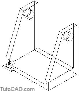
15) Pick Draw + Solids + Cylinder. Enter 1,0.5 as the center for the base of the cylinder. Invoke Diameter and enter 0.265 as the diameter. Then enter 0.25 as the height.
16) Pick Draw + Solids + Cone. Use a Center osnap near P1 as the center for the base of the cone. Invoke the Diameter option and enter 0.55 as the base diameter. Enter negative 0.275 as the height of the cone.
When you create countersunk holes with a 90 degree angle you can use half the diameter for the height (half of 0.55 is 0.275).
17) Pick Modify + Mirror and select the new cone and cylinder objects then press <enter>. Use a Midpoint osnap near P2 as the first point of the mirror line. Make sure POLAR is On in the status bar and left-click when the tooltip angle is 90 for the second point of the mirror line. Press <enter> to keep the source objects.
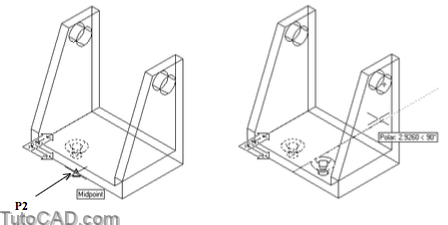
18) Pick Modify + Solids Editing + Subtract. Subtract the 2 new cylinders & 2 new cones from the main SOLID model.
19) Pick Draw + Solids + Box. Pick in empty space near P1 as the first corner. Enter L to invoke Length and use a length of 1.5, width of 1.0 and height of 0.25.

20) Pick Modify + Move. Enter L to select the Last SOLID and press <enter> to continue. Use Midpoint osnaps near P2 & P3 as the basepoint and second point.

21) Pick Modify + Solids Editing + Subtract. Subtract the box from the main SOLID to complete the model.
22) Save this model as My primitives.dwg in your personal folder and Close the file.
More practice?
» 23) Close the file from the previous exercise if it is still open.
» 24) Open the T304_5.dwg file in your personal folder. The objective of this exercise is to create a torus to model an o-ring as per the data supplied by the manufacturer below.

25) Pick Tools + New UCS + X & press <enter> to rotate the UCS about the World UCS X axis by <90> degrees so that the XY plane of the current UCS is perpendicular to the desired torus axis.
26) Pick Draw + Solids + Torus. Invoke a Near osnap and pick the axis LINE near P1 as the center for the torus. Invoke the Diameter option and enter 0.53125 as the torus diameter. Invoke the Diameter option again and enter 0.09375 as the tube diameter. The command line history is shown below.
Command: TORUS
Current wire frame density: ISOLINES=4
Specify center of torus <0,0,0>: (use Nearest osnap near P1)
Specify radius of torus or [Diameter]: D↵
Specify diameter: 0.53125↵
Specify radius of tube or [Diameter]: D↵
Specify diameter: 0.09375↵
Command:

27) Save the changes to the model and Close the file.
Still more practice?
» 28) Close the file from the previous exercise if it is still open.
» 29) Start a New drawing from Scratch using English defaults.
» 30) Create a new red Layer called Solid and make it current.
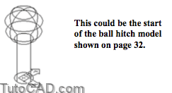
» 31) Pick Draw + Solids + Cylinder. Press <enter> to use the origin <0,0,0> for the cylinder base center. Enter D to invoke Diameter and enter a diameter of 1.5. Enter 5 as the height.
» 32) Pick View + 3D Views + SE Isometric.
» 33) Pick View + Zoom + Out to reduce the view magnificationby a factor of 2.
» 34) Pick Draw + Solids + Sphere. Use a Center osnap at the top of the cylinder as the center for the sphere. Invoke the Diameter option and enter 3 as the diameter. The command line history is shown.
Command: SPHERE
Current wire frame density: ISOLINES=4
Specify center of sphere <0,0,0>: (useCenterosnapnearP1)
Specify radius of sphere or [Diameter]: D↵
Specify diameter: 3↵
Command:

35) Pick Modify + Solids Editing + Union. Select both SOLID primitives and press <enter> to complete the task.
36) Save this model as Ball_hitch.dwg in your personal folder and Close the file.